MIL-PRF-15733/61G
Radiographic inspection (conformance only) (applicable to dash numbers 0011and 0016 only).
Filters shall be x-rayed in one plane at 90 degrees rotation perpendicular to their longitudinal axis. Any
evidence of poor capacitor mounting or uneven soldering of capacitor to case shall be cause for rejection;
rejected units shall be dissected and examined for poor workmanship or uneven soldering. Any defects noted
shall require corrective action prior to acceptance of future lots. Magnification during visual inspection shall be
2 power, minimum. Unless otherwise specified, one radiograph shall be taken of each unit. Filters shall be
positioned to yield a longitudinal image of the body.
Moisture resistance: Not applicable.
Part or Identifying Number (PIN): M15733/61-(dash number from table llI).
Marking: Each filter shall be marked with the PIN. In addition, full marking in accordance with MIL-PRF-15733
shall be marked on the unit package.
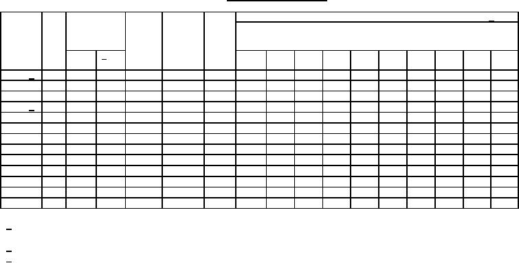
TABLE III. Electrical characteristics.
Minimum insertion loss (dB) in accordance with MIL-STD-220. 1/
+25°C
Dash
Cir-
Rated
Rated
Capac-
Volt-
number
cuit
voltage
current
itance
age
amps
(min)
drop
V dc
2/ V
1
5
10
20
50
100
200
500
1
10
pF
volts
rms
MHz
MHz
MHz
MHz
MHz
MHz
MHz
MHz
GHz
GHz
š
0001 3/
200
140
10
1,500
.1
----
----
----
----
32
45
58
70
70
70
š
0002
200
140
10
1,500
.1
----
----
----
----
32
45
58
70
70
70
š
0003
500
350
25
2,000
.5
----
----
----
----
40
55
65
70
70
70
š
0004 3/
500
350
25
2,000
.5
----
----
----
----
40
55
65
70
70
70
š
0006
200
140
10
1,500
.1
----
----
----
----
32
45
58
70
70
70
š
0007
100
70
10
5,000
.1
----
----
----
----
50
65
70
70
70
70
š
0008
100
70
10
1,000
.1
----
----
----
----
50
65
70
70
70
70
š
0009
70
----
10
12,000
.1
----
20
----
48
----
65
----
----
65
65
š
0011
100
70
10
5,000
.5
----
----
----
----
50
65
----
65
70
70
0013
100
----
10
22,000
.1
10
----
30
----
----
42
45
----
60
60
L2
š
0014
50
----
20
10,000
.5
----
----
20
----
50
65
70
----
70
70
š
0015
500
----
15
2,500
.15
----
----
5
----
----
50
55
----
70
70
š
0016
100
----
10
25,000
.1
----
15
----
60
60
65
----
65
65
65
1/ Insertion loss measurements between 1 MHz and 10 MHz, inclusive, shall be performed at full load.
Insertion loss measurements above 10 MHz shall be performed at no load.
2/ Zero to 400 Hz over the rated temperature range of -55°C to +125°C.
3/ Inactive for new design.
7