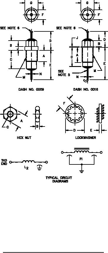
MIL-PRF-15733/61G
NOTES:
1. Circuit diagram is for information only.
2. Case is ground terminal.
3. Mounting hardware (lockwasher and hex nut) shall be supplied with each filter.
4. Terminal identification (nonsymmetrical filters): The case shall be marked at the threaded end of the filter,
with the symbol "L" for L2 circuits.
5. Hook bend radius: .046 (1.17 mm) (REF).
6. Turret head terminal is optional.
7. Potting shall not extend beyond .030 inch (0.76 mm) from the filter body.
8. An undercut or imperfect threads out to a maximum of .060 inch (1.52 mm) from the hex head or mounting
surface is permissible.
FIGURE 1. Filter and hardware dimensions and circuit configurations - Continued.
2