Dash
A
B
C
D
E
F
G
H
J
K
L
Weight
number
Max
(grams)
Ref
Ref
Min
Max
Max
Min
Max
Min
Max
Max
Min
Max
Max
Ref
Ref
1.2
0001
.600
.336
.097
.167
.030
.079
.109
.177
.222
.030
.173
.203
.211
.030
.060
(15.24)
(8.53)
(2.46)
(4.24)
(0.76)
(2.01)
(2.77)
(4.50)
(5.64)
(0.76)
(4.38)
(5.16)
(5.36)
(0.76)
(1.52)
A
B
C
D
E
F
G
H
J
K
1.2
0002
Min
Max
Ref
Min
Min
Min
Max
Ref
Ref
Min
Max
Min
Max
Max
0003
.390
.430
.200
.050
.050
.213
.263
.125
.062
.039
.045
.185
.191
.211
(9.91)
(10.92)
(5.08)
(1.27)
(1.27)
(5.41)
(6.68)
(3.18)
(1.57)
(0.91)
(1.14)
(4.70)
(4.85)
(5.36)
NOTES:
1. Dimensions are in inches.
2. Metric equivalents are given for general information only.
3. Circuit diagram is for information only.
4. Mounting torque 3 to 5 inch-pounds.
5. Case is ground terminal.
6. Mounting hardware (lockwasher and hex nut) will be supplied with filter.
7. Leads shall be solid, solder coated, AWG 18 (.040 inch).
8. Turret head terminal optional.
9. An undercut or imperfect threads out to a maximum of .052 inch from the hexhead or mounting surface is permissible.
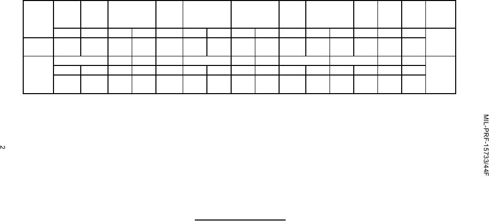
FIGURE 1. Case and circuit configuration - Continued.
For Parts Inquires call Parts Hangar, Inc (727) 493-0744
© Copyright 2015 Integrated Publishing, Inc.
A Service Disabled Veteran Owned Small Business