MIL-F-18327F
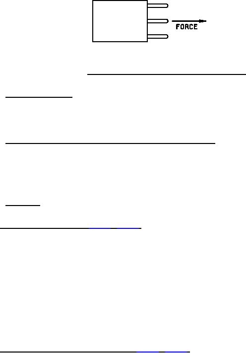
FIGURE 7. Direction of force to be applied to each pin on the unit.
4.7.2.2 Flat terminal bend test. Filters shall be tested in accordance with method 211, MIL-STD-202.
a.
Test condition letter: B.
b.
Number of bending cycles: 5.
4.7.2.3 Twist test (solid-wire load terminals other than printed circuit terminals). Filters shall be tested in
accordance with method 211, MIL-STD-202. Terminals shall be subjected to the twist test following completion of
their subjection to the pull test specified in 4.7.2.1.
a.
Test condition letter: D.
b.
Number of 360 degree rotations: Five (total of 1,800 angular degrees).
4.7.2.4 Torque test. Filters shall be tested in accordance with method 211, MIL-STD-202, test condition E. For
grades 4, 6, and 8, this test is applicable only to terminals with external screw threads.
4.7.3 Solderability (when specified, see 3.1) (see 3.6). Filters shall be tested in accordance with method 208, MIL-
a.
The number of terminations of each filter to be tested.
b.
Special preparation of terminals, if applicable.
c.
Application of standard solderable wire (if greater than No. 18 AWG size, or solid wire greater than .045
inch diameter).
d.
Depth of immersion if other than .05 inch.
e.
Solder dip dwell time.
f.
Examination of terminations which have been subjected to the test.
4.7.4 Resistance to soldering heat (when specified, see 3.1) (see 3.7). Filters shall be tested in accordance with
method 210, MIL-STD-202. The following detailed requirements shall be as specified (see 3.1):
a.
Use of heat sinks.
b.
Solder terminations that are not to be tested, if applicable.
c.
Special preparation of specimens, if applicable.
d.
Immersion of terminations in flux, if applicable.
22
For Parts Inquires call Parts Hangar, Inc (727) 493-0744
© Copyright 2015 Integrated Publishing, Inc.
A Service Disabled Veteran Owned Small Business