MIL-PRF-28861/5C
Inches
mm
Inches
mm
A
.003
0.08
.145
3.68
Dash
dimension
(±.010)
.005
0.13
.187
4.75
number
.007
0.18
.200
5.08
001
.010
0.25
.250
6.35
through
.187
.015
0.38
.312
7.92
012
.022
0.56
.395
10.03
013
.045
1.14
.408
10.36
.312
through
.070
1.78
.410
10.41
024
.093
2.36
.793
20.14
.115
2.92
NOTES:
1. Dimensions are in inches.
2. Metric equivalents are given for general information only.
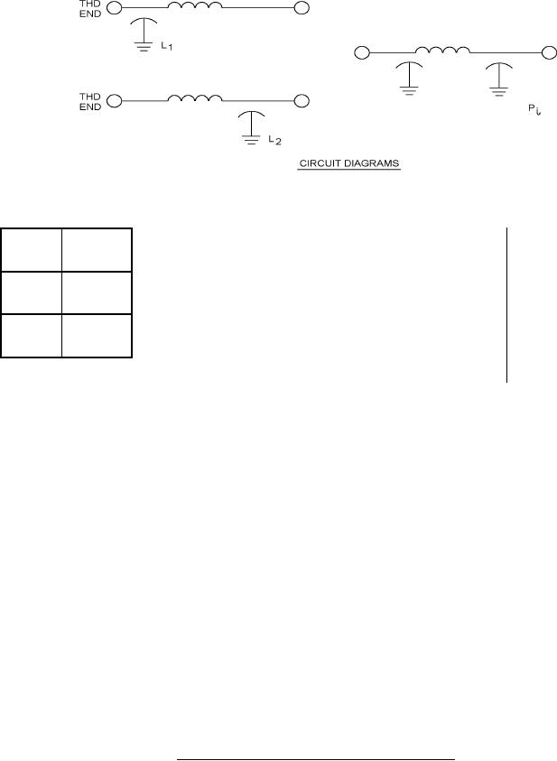
3. Circuit diagrams are for information only.
4. All filters shall be supplied with mounting hardware (hex nut and lockwasher). Mounting hardware shall be
furnished with the same finish as the filter case.
5. Terminal identification (nonsymmetrical filters): The case shall be marked at the threaded end of the filter
with the symbol "C" or the symbol "L" as follows, or the circuit diagram shall be marked on the case.
Circuit
Symbol
C
L1
L2
L
Optional slot may be supplied, .050 ± .010 inches (1.27 ± 0.25 mm) x .070 ± .010 inches (1.78 ± 0.25 mm).
6.
7.
Imperfect thread or undercut optional .050 inch (1.27 mm) maximum.
8.
One imperfect thread allowed .035 inch (0.89 mm) maximum.
Recommended mounting torque: 44 inch-ounces ± 4 inch-ounces.
9.
FIGURE 1. Case and hardware dimensions and circuit diagram - Continued.
2
For Parts Inquires call Parts Hangar, Inc (727) 493-0744
© Copyright 2015 Integrated Publishing, Inc.
A Service Disabled Veteran Owned Small Business