MIL-PRF-15733/75A
Inches
mm
.074
1.88
.190
4.83
.250
6.42
.375
9.53
.562
14.27
.625
15.88
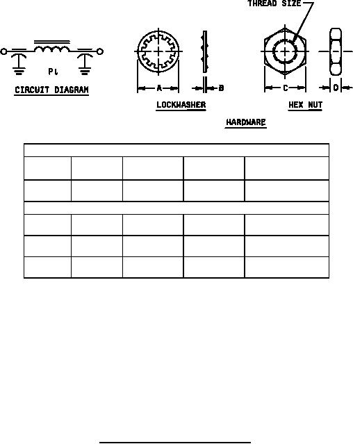
Mounting Hardware
D
C
B
A
Thread size
±.005
±.010
±.005
±.005
.375
.022
.375
.125
.190-32 UNF-2B
(9.53)
(.56)
(9.53)
(3.18)
Terminal Hardware
.330
.02
.344
.125
.164-32 UNC-2B
(8.38)
(.5)
(8.74)
(3.18)
.375
.022
.375
.125
.190-32 UNF-2B
(9.53)
(.56)
(9.53)
(3.18)
.472
.025
.437
.156
.250-20 UNC-2B
(11.99)
(.64)
(11.10)
(3.96)
NOTES:
1. Dimensions are in inches.
2. Metric equivalents are given for general information only.
3. Metric equivalents are in parentheses.
4. Circuit diagram is for information only.
5. Mounting hardware shall be supplied with filter.
6. Terminal hardware shall be supplied with filter.
7. Recommended mounting torque 192 oz-in maximum.
8. Tolerances, unless otherwise specified shall be ±.031.
9. Marking shall include the numbers shown in figure 1 next to the terminals.
FIGURE 1. Case dimensions and circuit diagram - Continued.
3
For Parts Inquires call Parts Hangar, Inc (727) 493-0744
© Copyright 2015 Integrated Publishing, Inc.
A Service Disabled Veteran Owned Small Business