MIL-F-18327F
4.7.8 Electrical characteristics (see 3.11). The electrical characteristics specified shall be determined with rated
voltage applied over the specified frequency range with the specified source and load impedance (see 3.1). Insertion
loss and discrimination characteristics shall be included for all filters. Special characteristics, such as impedance,
phase shift in the pass band, special stability, transient response, harmonic and intermodulation distortion limits, and
reflection coefficient and return loss shall be measured, when specified (see 3.1).
4.7.8.1 Terminal impedance (when specified, see 3.1). Terminal input impedance shall be measured with a rated
load connected across the output terminals of the filter. Terminal output impedance shall be measured with a rated
source impedance connected across the input terminals of the filter. Impedances including vector angles shall be
measured at the specified frequencies (see 3.1) by a bridge or equivalent method approved by the Government.
4.7.8.2 Insertion loss (see 6.5.4) (at reference frequency). The reference frequency and the source and load
impedances shall be as specified (see 3.1). With a constant input voltage, Eg, across the generator, the load voltage,
with and without the filter in the circuit, shall be recorded at the reference frequency. The insertion loss, in decibels,
shall be calculated using the following formula:
E1
ILfr = 20 log E2 dB, E1 > E2.
Where:
ILfr = Insertion loss at reference frequency in decibels, with Eg constant.
E1 = The load voltage with the filters not in the circuit at the reference frequency.
E2 = The load voltage with the filters in the circuit at the reference frequency.
E1 > E2.
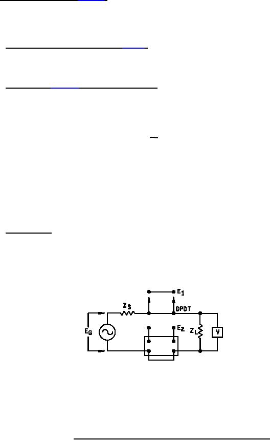
A typical test circuit is shown in figure 8.
4.7.8.3 Discrimination . Insertion loss at frequencies other than the reference frequency shall be measured using a
test circuit such as that shown on figure 8. Measurements shall be made at frequencies or over frequency bands, as
specified (see 3.1). The algebraic difference between the insertion loss at a specified frequency and the insertion
loss at the reference frequency, shall be defined as the discrimination (α) at the specified frequency.
ZS = Source impedance.
ZL = Load impedance.
EG = Constant voltage across generator.
E1 = The load voltage with the filter not in the circuit at the reference frequency.
E2 = The load voltage with the filter in the circuit at the same frequency.
FIGURE 8. Typical measurement circuit for insertion loss and discrimination.
24
For Parts Inquires call Parts Hangar, Inc (727) 493-0744
© Copyright 2015 Integrated Publishing, Inc.
A Service Disabled Veteran Owned Small Business