MIL-PRF-15733/67B
Inches
mm
Inches
mm
.003
0.08
.120
3.05
.005
0.13
.125
3.18
.006
0.15
.218
5.54
.010
0.25
.250
6.35
.015
0.38
.312
7.92
.020
0.51
.3125
7.938
.022
0.56
.371
9.42
.062
1.57
.430
10.92
.093
2.36
.702
17.83
NOTES:
1. Dimensions are in inches.
2. Metric equivalents are given for general information only.
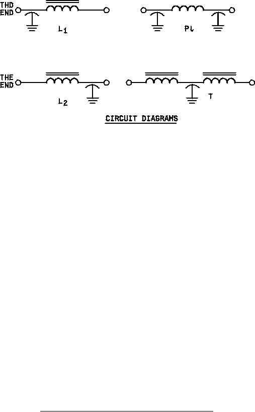
3. Circuit diagram is for information only.
4. All filters shall be supplied with mounting hardware.
5. Recommended mounting torque: 60 in.-oz. maximum.
6. Terminal identification (non-symmetrical filters): The case shall be marked at the threaded end of the filter, with the
symbol "C" or the symbol "L", as follows:
Circuit
Symbol
L1
C
L2
L
FIGURE 1. Case dimensions, mounting hardware and circuit diagrams - Continued.
2
For Parts Inquires call Parts Hangar, Inc (727) 493-0744
© Copyright 2015 Integrated Publishing, Inc.
A Service Disabled Veteran Owned Small Business