MIL-PRF-15733/25C
Inch
mm
Inch
mm
.005
.13
.145
3.68
.010
.25
.187
4.75
.015
.38
.200
5.08
.025
.64
.312
7.92
.045
1.14
.416
10.57
.050
1.27
.738
18.75
.070
1.78
.743
18.87
.093
2.36
.793
20.14
.109
2.77
1.179
29.95
1.345
34.16
NOTES:
1. Dimensions are in inches.
2. Metric equivalents are given for general information only.
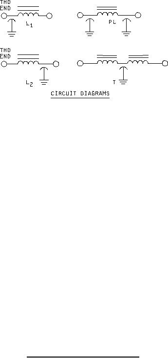
3. Circuit diagram is for information only.
4. All filters shall be supplied with mounting hardware.
5. Use of styles FL13 with or without shoulder is optional.
6. Terminal identification (non-symmetrical filters): The case shall be marked at the threaded end of the filter with
the letter "C" or "L" as follows:
Letter
Circuit
C - - - - - - - - - - - - - -L1
L - - - - - - - - - - - - - -L2
7. Imperfect threads or undercut permitted out to a maximum of .052 (1.32 mm) from the mounting surface.
FIGURE 1. Case dimensions and circuit diagrams - Continued.
2
For Parts Inquires call Parts Hangar, Inc (727) 493-0744
© Copyright 2015 Integrated Publishing, Inc.
A Service Disabled Veteran Owned Small Business