MIL-PRF-15733/23B
DIMENSION
A = .630 inches max
A = .730 inches max
B ± .010
B ± .010
.312
.187
.312
.187
Dash no.
Dash no.
Dash no.
Dash no.
0001
0031
0002
0032
0005
0006
0003
0033
0004
0034
0011
0012
0007
0037
0008
0038
0017
0018
0009
0039
0010
0040
0023
0024
0013
0043
0014
0044
0029
0030
0015
0045
0016
0046
0035
0036
0019
0049
0020
0050
0041
0042
0021
0051
0022
0052
0047
0048
0025
0055
0026
0056
0053
0054
0027
0057
0028
0058
0059
0060
NOTES:
1. Dimensions are in inches.
2. Metric equivalents are given for general information only.
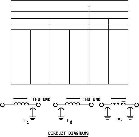
3. Circuit diagrams are for information only.
4. All filters shall be supplied with mounting hardware.
5. Use of styles FL10 or FL11 with or without shoulder is optional.
6. Terminal identification (non-symmetrical filters): The case shall be marked at the threaded end of the filter with
the symbol "C" or "L" as follows:
Symbol
Circuit
C - - - - - - - - - - - - - L1
L - - - - - - - - - - - - - L2
7. Optional terminal hole of .070 ± .010 inch or terminal slot of .050 ± .010 x .070 ± .010 inch may be supplied.
FIGURE 1. Case dimensions and circuit diagrams - Continued.
2