MIL-F-15733/64A
A
B
C
D
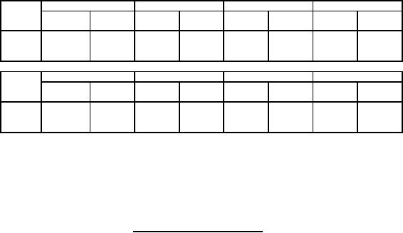
Dash
number
Min
Max
Min
Max
Min
Max
Min
Max
Dia
0001
1.049
1.111
.240
.260
---
.125
.405
.425
(26.64)
(28.22)
(.610)
(.660)
(3.18)
(10.29)
(10.80)
Dash
E
F
G
H
number
Min
Max
Min
Max
Min
Max
Min
Max
0001
.405
.425
.105
.125
.390
.410
---
.010
(10.29)
(10.80)
(2.67)
(3.18)
(9.91)
(10.41)
(.25)
NOTES:
1. Dimensions are in inches.
2. Metric equivalents are in parentheses and are given for general information only.
3. Circuit diagram is for information only.
4. Leads shall be solid, solder-coated, AWG 20 .032 (.81 mm) diameter.
Figure 1. Case and circuit configuration (continued).
REQUIREMENTS:
Dimensions and configuration: See figure 1.
Weight: 0.7 gram maximum.
Case: Metallic mounting strap.
Terminals: Solderable. Pure tin finish is prohibited.
Operating temperature range: -55° to +125°C.
Rated voltage: 70 V dc.
Rated current: 10 amperes, dc.
DC resistance: 0.01 ohm maximum.
Seal: Not applicable.
Capacitance to ground: In accordance with MIL-PRF-15733. Measured capacitance shall be at least 12,000 pF.
Temperature rise: +25°C maximum.
Dielectric withstanding voltage: In accordance with MIL-PRF-15733 except the test voltage of 200 V dc shall be
applied for 1 to 5 seconds.
Barometric pressure (reduced): In accordance with MIL-PRF-15733 and method 105, MIL-STD-202; test condition B
(50,000 ft). The following exception shall apply:
Dielectric withstanding voltage: In accordance with initial requirements, except that test voltage shall be 1.2 times
rated dc voltage.
Insulation resistance: In accordance with MIL-PRF-15733. The insulation resistance measured at 25°C between
both terminals connected together and the case shall be at least 5,000 megohms.
2
For Parts Inquires call Parts Hangar, Inc (727) 493-0744
© Copyright 2015 Integrated Publishing, Inc.
A Service Disabled Veteran Owned Small Business