MIL-F-15733/4J
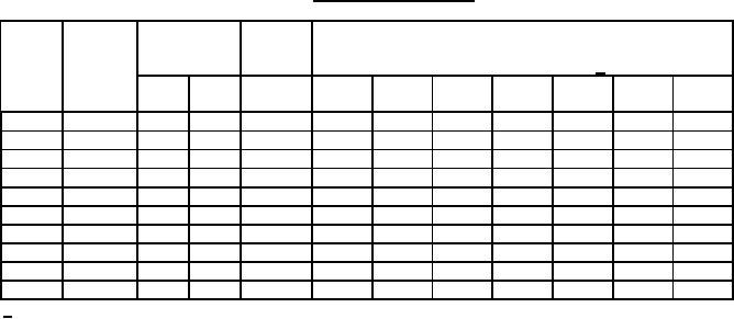
Table I. Electrical characteristics.
Minimum insertion loss (dB) in accordance with
Rated
Rated
Circuit
Dash
MIL-STD-220 at +25°C 1/
current
voltage
diagram
number
V dc
V ac
(A)
.15
.30
.60
1
10
100
1,000
MHz
MHz
MHz
MHz
MHz
MHz
MHz
š
0001
400
125
1
50
60
60
60
60
60
60
š
0002
400
125
3
50
60
60
60
60
60
60
š
0003
400
125
5
50
60
60
60
60
60
60
š
0004
400
125
10
50
60
60
60
60
60
60
š
0005
400
125
15
40
50
60
60
60
60
60
š
0006
400
125
15
50
60
60
60
60
60
60
š
0007
400
125
30
40
50
60
60
60
60
60
š
0008
400
125
30
50
60
60
60
60
60
60
š
0009
400
125
55
40
50
60
60
60
60
60
š
0010
400
125
55
50
60
60
60
60
60
60
1/ Full load insertion loss measurements shall be made at frequencies between 150 kHz and 10 MHz .
Above 10 MHz, insertion loss measurements shall be made under no-load conditions.
REQUIREMENTS:
Dimensions and configuration: See figure 1.
Case finish: In accordance with MIL-PRF-15733. Pure tin finish is prohibited.
Operating temperature range: -65°C to +85°C.
Rated voltage: 125 volts ac; 400 volts dc.
Rated current: See table I.
Rated frequency: 0-400 Hz.
Insertion loss: In accordance with MIL-PRF-15733 and table I.
Seal: In accordance with MIL-PRF-15733.
Temperature rise: 25°C maximum for parts rated 10 amperes and less.
35°C maximum for parts rated greater than 10 amperes.
Insulation resistance: In accordance with MIL-PRF-15733 and the following:
Dash numbers 0001 through 0003 - 1000 megohms
Dash numbers 0004 through 0010 - 500 megohms
Maximum voltage drop: .5 volt.
Terminal strength: In accordance with MIL-PRF-15733 and the following:
Method 211, MIL-STD-202 - Test condition A: 9 pounds.
Method 211, MIL-STD-202 - Test condition B: 5 bends.
Method 211, MIL-STD-202 - Test condition E (threaded stud terminals only).
3
For Parts Inquires call Parts Hangar, Inc (727) 493-0744
© Copyright 2015 Integrated Publishing, Inc.
A Service Disabled Veteran Owned Small Business